The World Depends on Sensors and Controls
*
Contacts


Products
 
 
Support
 
 
See Also


Positive Temperature Coefficient (PTC) sensor
A Positive Temperature Coefficient (PTC) sensor provides the airflow sensing function. PTC sensors remain at a low, relatively constant level of resistance over a wide temperature range then abruptly increase resistance logarithmically at an elevated temperature known as an anomaly temperature. As the transition is approached, a slight temperature rise causes a dramatic increase in resistance.

Power supplied to the PTC sensor will cause it to self–heat to a high resistance condition. Sufficient airflow will cool the sensor to its low resistance level. Insufficient airflow allows the sensor to self–heat and reach a high resistance state. This resistance change and accompanying decrease in current is used to trigger an output transistor or SCR.

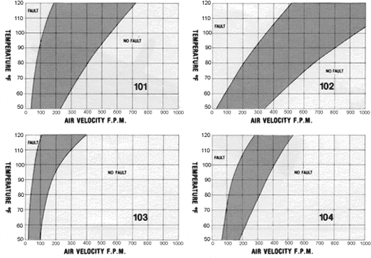
Definitions for the Temperature vs. Velocity Curve (at right)
No–Fault: Operation points within this region represent the normal state. (i.e. sufficient airflow to cool sensor to its low resistance level.)
Fault: Operating points within this region represent the anomaly state. (i.e. Insufficient airflow allows sensor to reach high resistance state.)


Site Updated February 16, 2018

* * * Sensata > Products > Klixon Brand > Airflow Sensors >

2SE Klixon® Solid–State Vane Switch


Solid–state
High reliability
Commercial or military grades
Variety of switching modes


The Klixon 2SE solid–state vane switch has advanced, state-of-the-art airflow sensing. Successor to electromechanical vane types, the 2SE is designed to sense and protect against the loss of airflow in power supplies, data processing units, or any other commercial or military electronic equipment where it is necessary to recognize the loss or reduction of airflow.

* * *
Klixon
2SE Airflow Sensors

Spec Overview
Supply Voltage
30 VDC maximum
Switching Capacity
400 milliamps maximum
Configuration
SPST or DPST
Reset
Automatic or Manual
Mode
Normally open or closed
Weight
Approximately 20 grams
Power Dissipation
Approximately 3 watts
Life
100,000 cycles
Operating Temp. Range
10°C to 50°C (50°F to 120°F)
Ambient Temp. Range
Up to 150°C (300°F)
Vibration
10G, 10–500 Hz per MIL-STD-202, Method 202, Condition A
Shock
100G, for 6ms per MIL-STD-202, Method 213, Condition C
Humidity
10 days per MIL-STD-202, Method 106
Salt Spray
48 Hours per MIL-STD-202, Method 101, Condition B


Temperature vs. Velocity Curve
Note: The gray region is the deadband, in which sensor could be in either the fault or the no–fault condition. Number on curve is for building part number of device. (Scroll down for information on building a part numbers, see at left for definitions.)
Chart

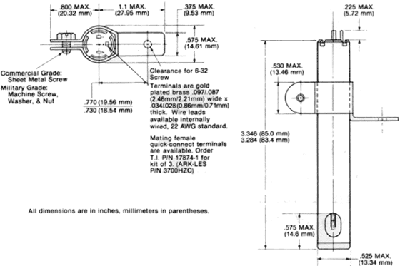
Configuration
Below is the typical 2SE configuration, but others are available. Drawing is for reference only.

Chart
The World Depends on Sensors and Controls