|
|
Klixon 7270 and 7271 Series |
|
|
Aircraft Circuit Breakers |
| – |
|
|
| – |
|
|
|
 |
|
|
 |
|
|
About these pages
Sensata Technologies is in the process of updating our web pages. Please bear with us during this process. If you have questions or comments, we’d like to hear from you. Please see contact us.
|
|
|
|
|
Sensata > Products > Klixon Brand > Circuit Breakers > Aircraft >
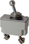
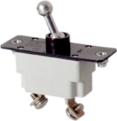
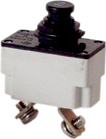
Klixon® 7270 and 7271 series
Toggle switch or pushbutton, single–phase
| Features and Overview |
/\ Top |
|
• |
Trip–free operation |
• |
Snap–acting thermal element |
• |
Small size |
• |
Light weight |
• |
MIL-C-5809 qualified |
• |
Current rating: 3 to 35 amps |
• |
High interrupting capacity |
|
|
• |
Available with neck mounting (7270-1 and 7271-8 devices) or standard cover
plate (7270-7 and 7271-3 devices) |
• |
Typical use: Aircraft and ground support equipment |
|
Klixon 7270 and 7271 series circuit breakers were designed to utilize less space behind the panel while protecting wire and cable in aircraft and ground support equipment on 120 VAC, 400 Hz or 30 VDC systems.
Inherently resistant to shock and vibration, the Klixon disc element is capable of calibration within close tolerances throughout the service life of the breaker.
|
| Performance Characteristics |
/\ Top |
|
Vibration |
10G minimum, 50–500 Hz (other vibration levels available) |
Mechanical Shock |
30G |
Acceleration |
10G |
Weight |
39 grams maximum (7270-1 and 7271-8) |
Interrupt Current |
4,000 amps at 30 VDC
3,500 amps at 120 VAC, 400 Hz
|
Endurance |
5,000 cycles: 120 VAC. 400 Hz, inductive
5,000 cycles: 120 VAC 400 Hz, resistive
5,000 cycles: 30 VDC, inductive
2,500 cycles: 30 VDC, resistive
5,000 cycles: Mechanical, no load |
|
|
|
|
|
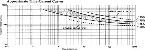
| Calibration Chart For a Standard Device |
/\ Top |
|
Temp. |
Minimum Ultimate Trip |
Maximum Ultimate Trip |
Trip Time in seconds |
200% |
500% |
1000% |
25°C |
105% |
145% |
15–65 |
2–10 |
1.4 |
-40°C |
138% |
175% |
15–65 |
2–10 |
1.4 |
70°C |
80% |
125% |
15–65 |
2–10 |
1.4 |
| The most typical device is 3–35 amps. For others, please contact us. |
| Calibration Chart By Amps |
/\ Top |
|
Amps |
Calibration at 25°C |
200% |
400% |
600% |
3 amps |
40–120 seconds |
3–26 seconds |
1–12 seconds |
5 amps |
40–100 seconds |
3–22 seconds |
1–10 seconds |
7.5 amps |
10–70 seconds |
0.75–7.0 seconds |
0.25–2.5 seconds |
10 amps |
10–70 seconds |
0.75–7.0 seconds |
0.25–2.5 seconds |
15 amps |
10–70 seconds |
0.75–7.0 seconds |
0.25–2.5 seconds |
20 amps |
10–70 seconds |
0.75–7.0 seconds |
0.25–2.5 seconds |
25 amps |
10–70 seconds |
0.75–7.0 seconds |
0.25–2.5 seconds |
30 amps |
10–70 seconds |
0.75–7.0 seconds |
0.25–2.5 seconds |
35 amps |
10–70 seconds |
0.75–7.0 seconds |
0.25–2.5 seconds |
| Drawings and Dimensions For Reference Only |
/\ Top |
|
7270X |
Device Type |
Envelope Drawing |
7270d1 |
- - - |
|
7271d3 |
- - - |
|
7270d8 |
- - - |
|
 |
| Spec Sheets For Our Most Popular Devices |
/\ Top |
|
| Specification sheets contain detailed drawings, amp ratings, characteristics, and more... |
7270X |
Device Type |
Spec Sheet |
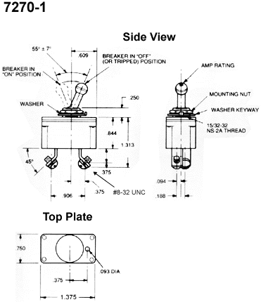
7270-1 |
- - - |
|
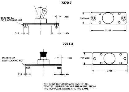
7270-7 |
- - - |
|
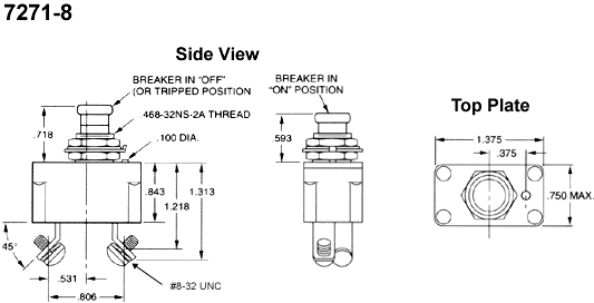
7271-8 |
- - - |
|
| For others, please contact us. |
|